
Dynamic Obstacle Avoidance (DOA)
Dynamic Obstacle Avoidance (DOA) is able to slightly alter the user's default path of AMRs if the default path is blocked by an obstacle, so that AMRs can continue to move without hitting the obstacle. This is a powerful feature to reduce human intervention and AMRs down time due an unforeseen obstacle is misplaced onto the default path, especially a trunk path.
Requirement
| Hardware | |
|---|---|
| Robot Type | Trackless |
| Obstacle Sensor | 2D Lidar with scan data |
| Software | |
| NavWiz | V3.1.0 patch v3.0 and above |
Setup
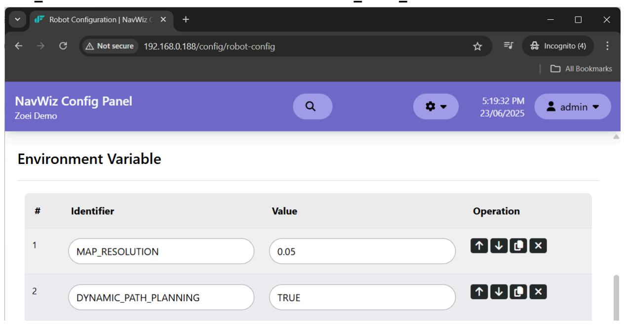
- In web user interface /config/robot-config, add a new Environment Variable of MAP_RESOLUTION with value of 0.05 and DYNAMIC_PATH_PLANNING with value of TRUE.
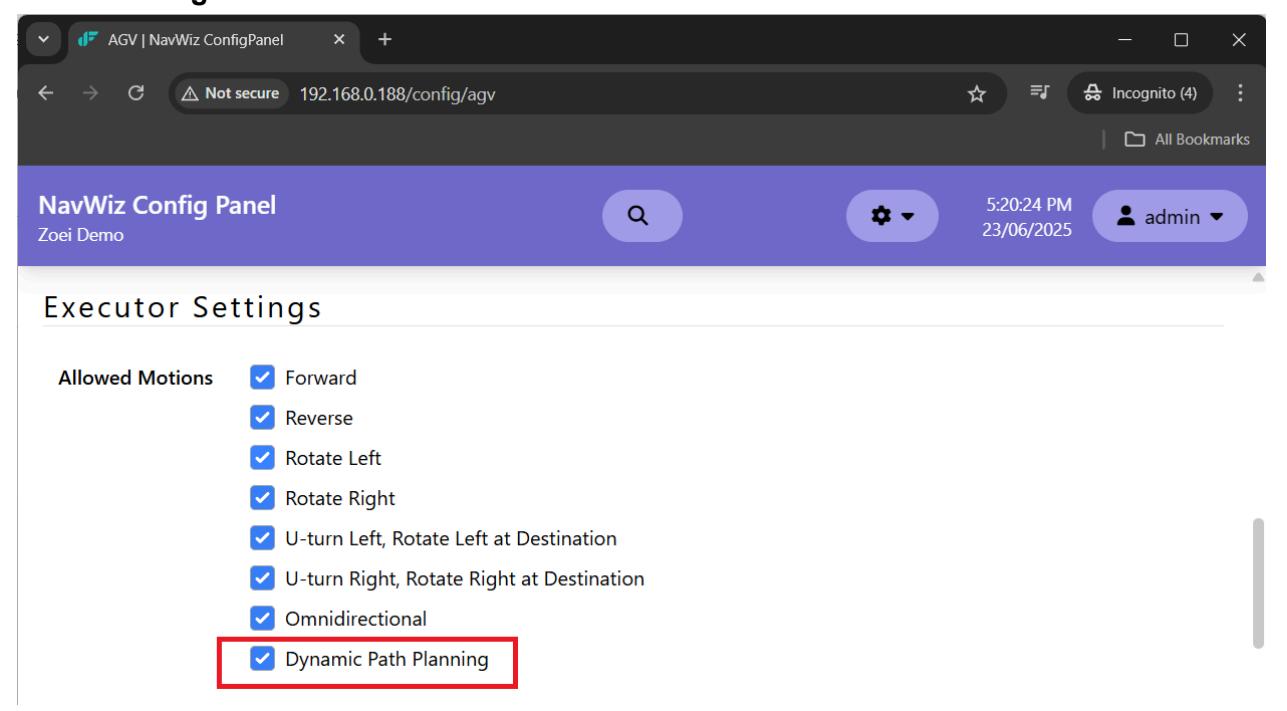
- In web user interface /config/agv, in Executor Settings check Allowed Motions of Dynamic Path Planning.
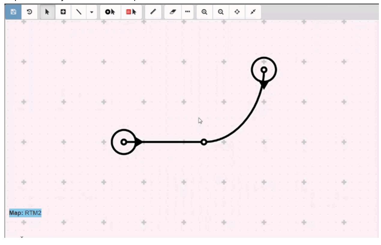
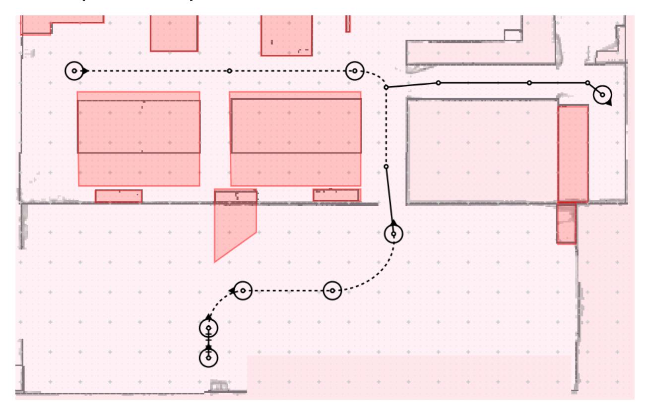
Dynamic Default Path
Represented by Dash Line in map.
Forbidden Zone
Forbidden zones are areas where AGV must NOT travel into during dynamic path following. The usages of forbidden zone are: 1. Act as a virtual wall or fence to avoid AGV dynamically traveling out from an area. 2. To cover any static obstacle which cannot be detected by 2D laser sensors. 3. To cover the area of holes and cliffs.
Example in Map
Example in Map.
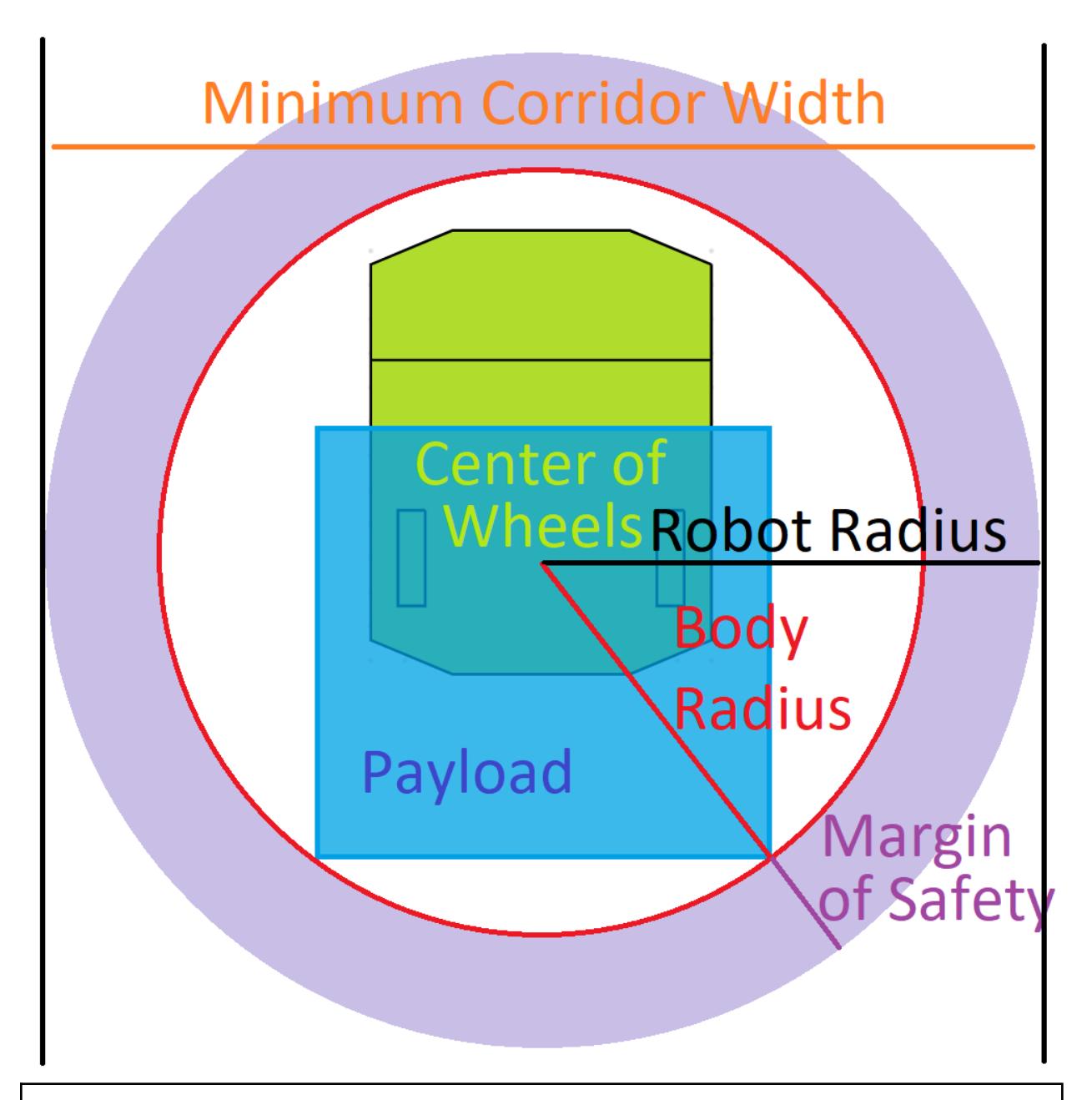
Robot Radius
Robot Radius = Body Radius + Margin of Safety Body Radius is the maximum distance from Center of Wheels to all body parts of AGV with Payload. Margin of Safety is essential for unsensible parts of dynamic obstacles. It is also important to have space for deceleration before hitting dynamic obstacles.
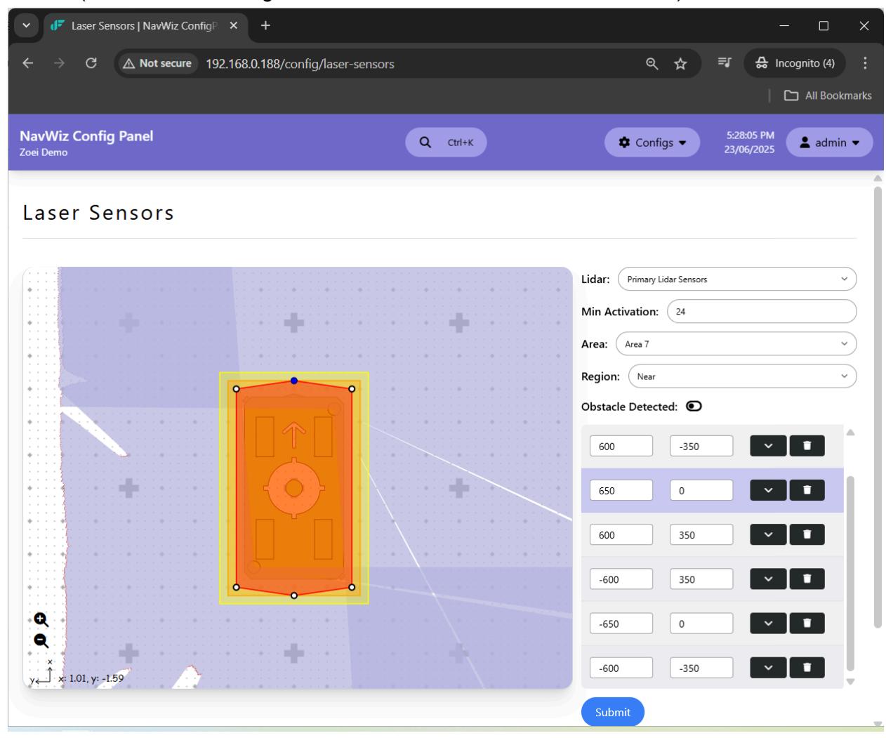
Laser Sensors
In /config/laser-sensors, Region: Near for dynamic actions must be within the circle of Robot Radius (calculated according to value set as in AGV Dimension Profiles).
Parameter List
In /config/parameters/agv05_obstacle_sensor/edit, up to 10 profiles with different values of Robot Radius and Safety Areas can be stored and selected during runtime.
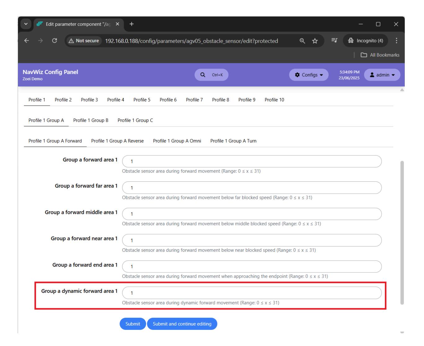
Group [a-c] dynamic forward area [1-10]
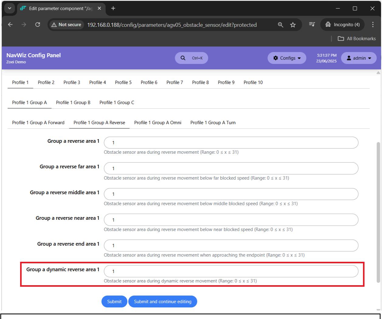
Group [a-c] dynamic reverse area [1-10]
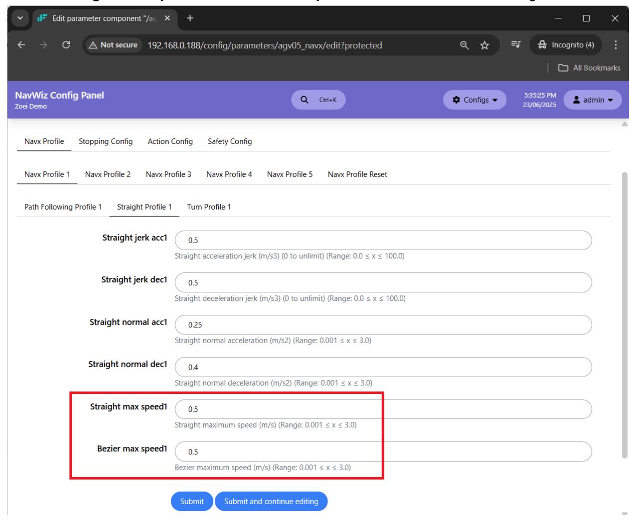
In profile for dynamic path planning, e.g. Navx Profile 1 in /config/parameters/agv05_navx/edit, limit the Straight max speed and Bezier max speed to the same value according to use case.
In Dynamic Path Planning Action Config of /config/parameters/agv05_navx/edit, update the settings accordingly.
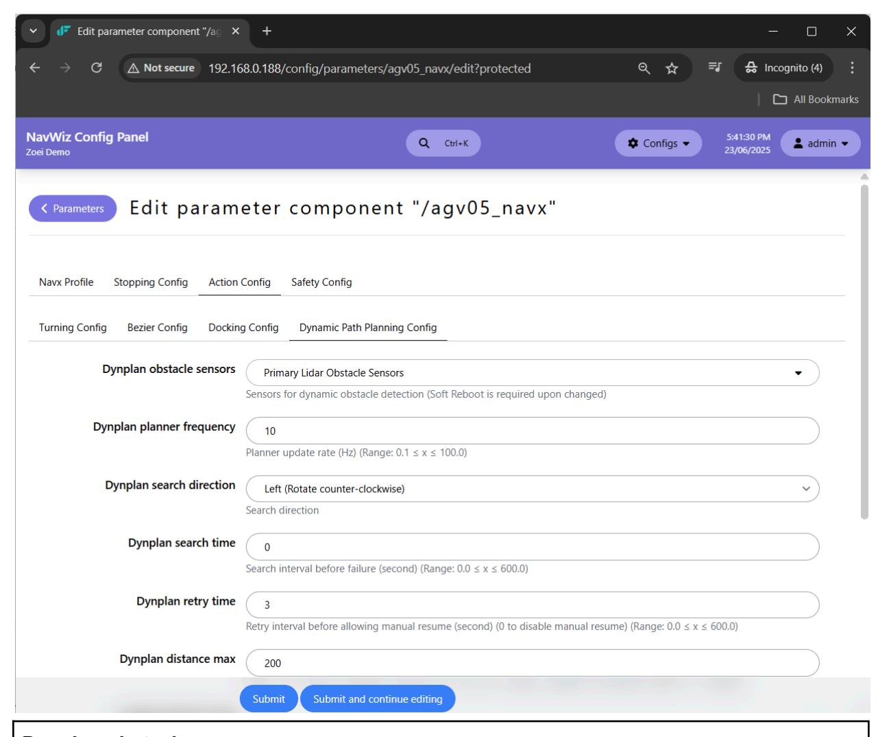
Dynplan obstacle sensors - Obstacle sensors to be used during dynamic path planning. - Must select at least one and then perform soft-reboot.
Dynplan planner frequency - Planner update rate. - Map resolution 50mm: 4Hz ~ 10Hz - Map resolution 20mm: 2Hz ~ 4Hz - Typical: Start testing with 10Hz and gradually reduce if System Overload triggered.
Dynplan search direction - Direction of on spot rotation when there is no valid path found if Dynplan search time is non 0.
Dynplan search time - Timer in second for on spot rotation when there is no valid path found before prompting Safety Trigger – Path blocked. - Set to 0 to disable. - Typical: 0
Dynplan retry time - Timer in second before user resume is allowed for Safety Trigger – Path blocked. - Set to 0 to disable manual resume. - Safety Trigger – Path blocked will be auto-resumed if no other Safety Triggered at the same time. - Typical: 3s
Dynplan distance max - Maximum distance of dynamic path, in term x% of static pre-planned path. - x% is greater than 100%. - Typical: 200%
Dynplan tolerance path - Distance error tolerance from dynamic constrained path in meter. - Typical: 0.15m
Dynplan tolerance mid - Midway junction tolerance in meter. - If AGV is within the tolerance from the target midway junction of the current dynamic path, it will start to travel on the next dynamic path. - Typical: 0.5m
Dynplan tolerance goal - Default stopping junction tolerance in meter. - In case the target stopping junction is blocked with an obstacle, the planner will attempt to create a plan with a goal position which is within tolerance from the target stopping junction. - Must be smaller than Straight out of path distance in /config/parameters/agv05_navx/edit#miscellaneous-config. - Typical: 0.1m
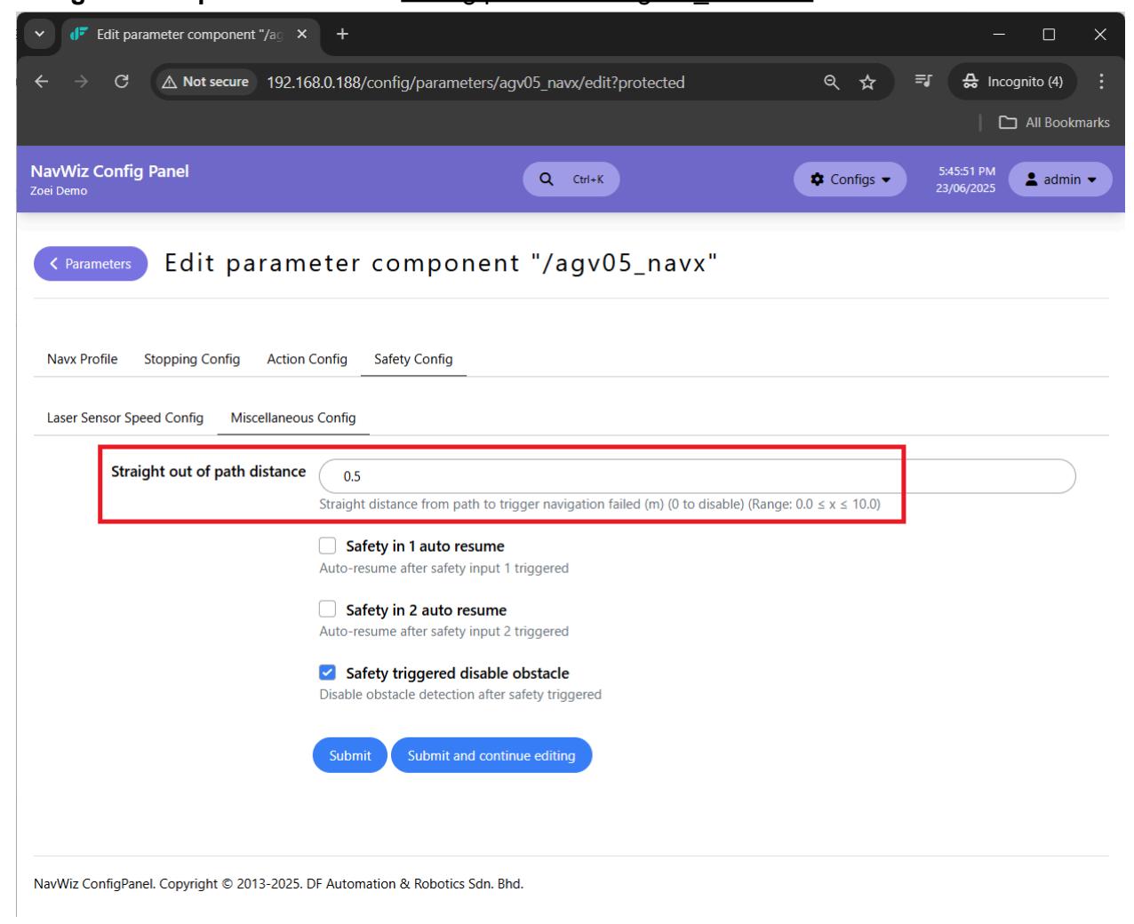
To increase or decrease the preferred zone border of the dynamic path planning, change Straight out of path distance in /config/parameters/agv05_navx/edit.
To change the waiting distance from the obstacle during Safety Trigger – Path blocked, change Max obstacle range in /config/parameters/agv05_navx/costmap/obstacle_layer/edit.
Max obstacle range - The maximum distance in meters from the sensor at which an obstacle will be inserted into the cost map. - Typical: 3m
If the obstacle sensors have blind spots and AMR occasionally hits obstacles at its blind spots even though these obstacles have been sensed just a few seconds ago, parameters in /config/parameters/agv05_navx/costmap/obstacle_layer/edit can be altered.
Footprint clearing enabled - Uncheck to disable clearing of the lethal obstacles found within robot footprint radius. - Typical: ✔
Obstacle timeout - Timer in second before a registered obstacle by 3D camera in costmap is removed. - Set to 0 to have all registered obstacles can only be cleared manually or after action done. - Typical: 30s
Raytrace timeout - Timer in second before a registered obstacle by 2D LiDAR in costmap is removed. - Set to 0 to have all registered obstacles can only be cleared by obstacle sensors or manually or after action done. - Typical: 0
Decay model - The time decaying model as the distance in between obstacles and AGV increases. - Constant : All registered obstacles will have the same decaying time of Obstacle timeout or Raytrace timeout: $t=t_{\scriptscriptstyle \Omega}$ - Linear : The decaying time is reduced linearly starting from Obstacle timeout or Raytrace timeout: $t = t_0(1 - 0.2d)$ - Exponential : The decaying time is reduced exponentially starting from Obstacle timeout or Raytrace timeout: $t = t_0 \left[ e^{-0.2d^2} \right]$ - Typical: Constant
If AMR occasionally overshoots and is stuck forever within the inscribed inflated region of obstacles (or even sensing noise), parameters in /config/parameters/agv05_navx/costmap/inflation_layer/edit can be altered.
Footprint clearing enabled - Check to enable clearing of the inscribed inflated obstacles found within robot footprint radius. - Typical: ✔
Golden value can be used for all of the parameters which are not in the list below.
Zalpha with 180° Lidar /config/parameters/agv05_navx/edit#dynamic-path-planning-config - Dynplan retry time: 3
/config/parameters/agv05_navx/costmap/obstacle_layer/edit - Footprint clearing enabled: Unchecked - Raytrace timeout: 0
/config/parameters/agv05_navx/costmap/inflation_layer/edit - Footprint clearing enabled: Checked
Task Skills
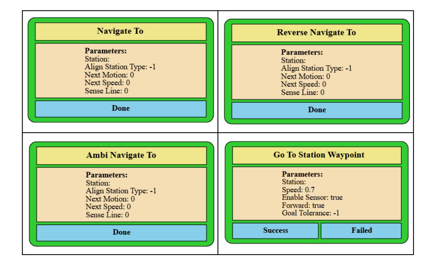
Station - Destination station. Align Station Type - Station alignment. - 0 : front line sensor. - 1 : rear line sensor. - -1 : trackless localization. Next Motion - Next motion after the final junction. - 0 : Idle - 1 : Non-Stop - 2 : Rotate Left - 3 : Rotate Right - 4 : Bezier Path Next Speed - Maximum moving speed in meters per second after the final junction. Sense Line - Sense line option. - 0 : Disable. - 1 : Stop after reaching the distance past the line. - 2 : Stop immediately when the line is sensed. - 3 : Stop after reaching the distance past the full line. - 4 : Stop immediately when the full line is sensed. Speed - Maximum moving speed in meters per second. Forward - true : Forward motion. - false : Reverse motion. Enable Sensor - true : Enable obstacle sensor. - false : Disable obstacle sensor. Goal Tolerance - Goal tolerance in meters from end position. - Values equal or greater than 0 will be used directly. - -1 : Dynplan tolerance mid. - -2 : Dynplan tolerance goal.
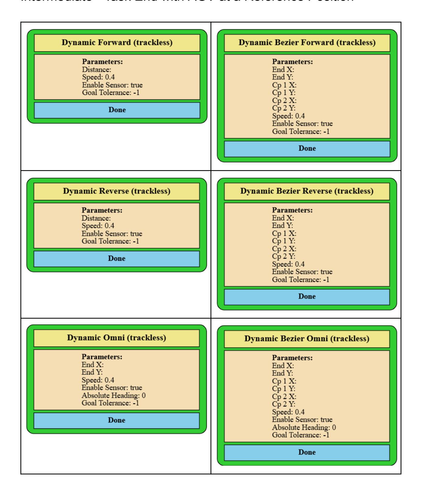
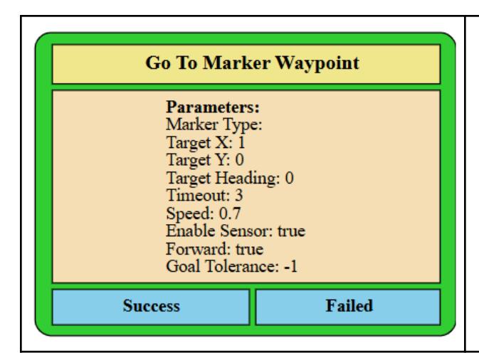
Distance - Distance in meters to move. End X - End position X (positive to front of AGV) in meters from center of wheels of AGV. End Y - End position Y (positive to left of AGV) in meters from center of wheels of AGV. Cp1 X - Bezier curve 1st control point X (positive to front of AGV) in meters from center of wheels of AGV. Cp1 Y - Bezier curve 1st control point Y (positive to left of AGV) in meters from center of wheels of AGV. Cp2 X - Bezier curve 2nd control point X (positive to front of AGV) in meters from center of wheels of AGV. Cp2 Y - Bezier curve 2nd control point Y (positive to left of AGV) in meters from center of wheels of AGV. Marker Type - Refer to Docking Actions. Target X - X coordinate of the target (in meters) in the marker frame (positive to front of marker). Target Y - Y coordinate of the target (in meters) in the marker frame. Target Heading - Target heading (in degrees) in the marker frame. - -1 : random final AGV heading. Timeout - Timeout duration in seconds. Speed - Maximum moving speed in meters per second. Forward - true : Forward motion. - false : Reverse motion. Absolute Heading - 0 : Forward motion. - -1 : Reverse motion. - 1-360 : Lock heading in degrees with respect to map. Enable Sensor - true : Enable obstacle sensor. - false : Disable obstacle sensor. Goal Tolerance - Goal tolerance in meters from end position. - Values equal or greater than 0 will be used directly. - -1 : Dynplan tolerance mid. - -2 : Dynplan tolerance goal.
Example in Map.
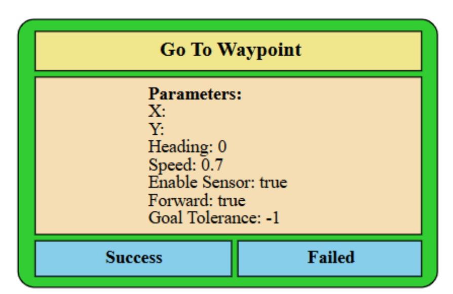
X - Coordinate X reference to map. Y - Coordinate Y reference to map. Heading - Final AGV heading in degree with respect to map. - 0 : random final AGV heading. Speed - Maximum moving speed in meters per second. Forward - true : Forward motion. - false : Reverse motion. Enable Sensor - true : Enable obstacle sensor. - false : Disable obstacle sensor. Goal Tolerance - Goal tolerance in meters from end position. - Values equal or greater than 0 will be used directly. - -1 : Dynplan tolerance mid. - -2 : Dynplan tolerance goal.
Once activated, touch on map to set target position, and optional drag before releasing touch on map to set final heading of AGV.
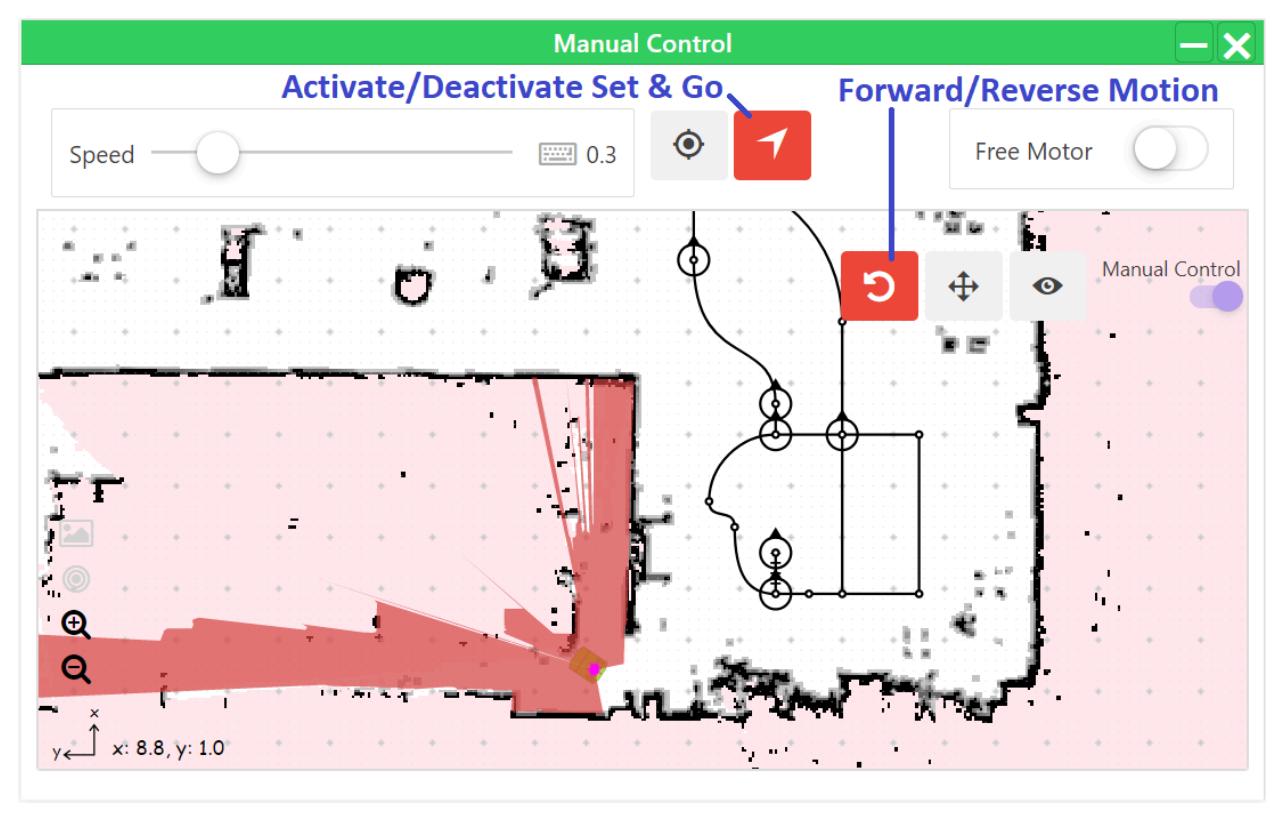
Example in Map.
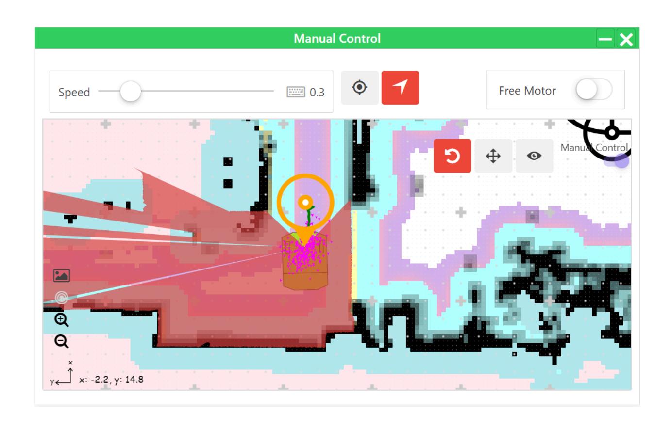
Precautions
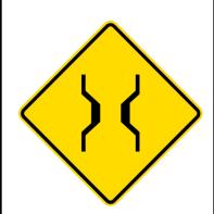
The software is using a map grid resolution of 0.05 m. Minimum Corridor Width = 2 x Robot Radius + 0.15 m.
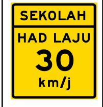
If there is a dynamic obstacle moving at high speed in the environment, AGV has to move at slow speed or it may hit the dynamic obstacle which jumps into its way.
Limitations
Zalpha with 180° Lidar With 0 value of Raytrace timeout, Zalpha with 180° lidar is not able to plan a path to a target position in its blind spot even after the removal of the obstacle at the target position. The only solution for this is to manually clear the obstacle that blocks the sight towards target position or manual resume from the user interface.
Test Results
List of related tests which have been carried out: - TRF 1.00.00079 Dynamic Path Planning - TRF 1.00.0098 Dynamic Path Planning for Zalpha with 180deg Lidar - TRF 1.00.0099 Limitations of Dynamic Path Planning for Zalpha with 180deg Lidar